Helpful Tools

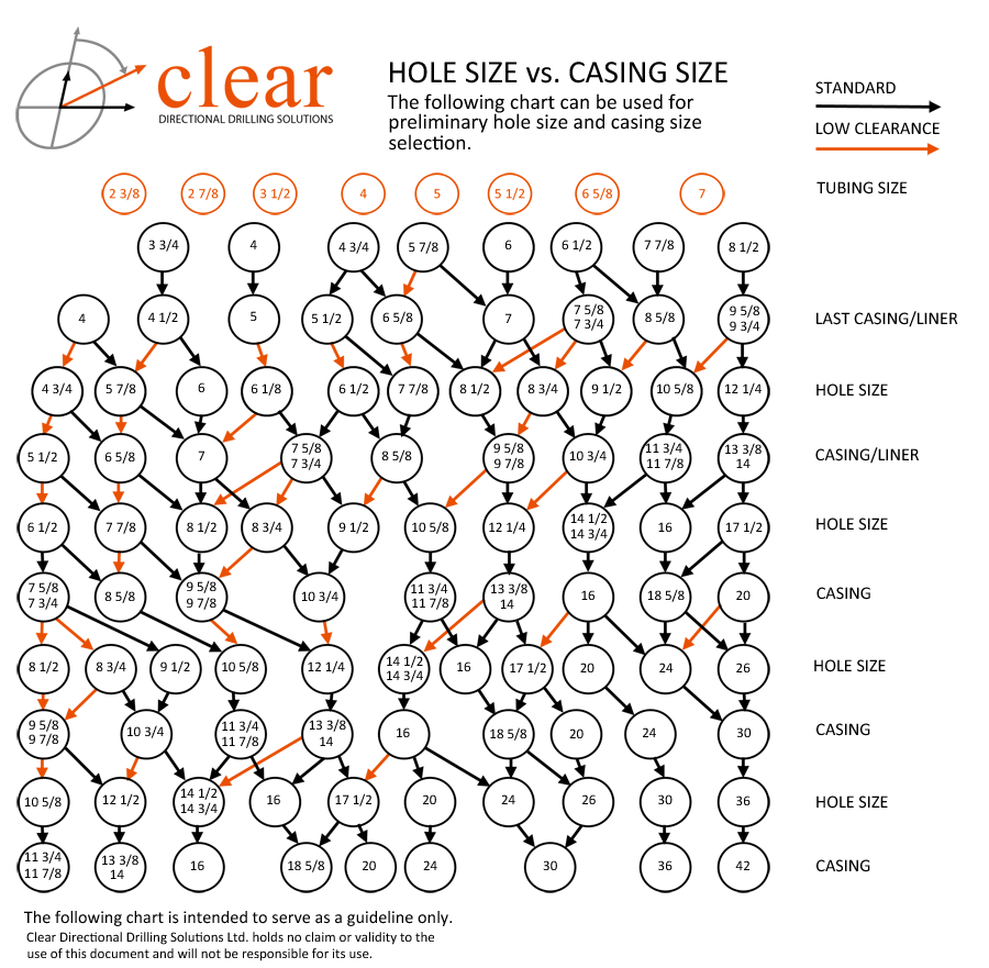
Below are various tools that are useful in regards to directional drilling:


Build Rate Calculation Web App


Unit Conversion Web App


Triplex Pump Output Calculator


Tie On Adjustment for Slant Drilling

Clear Directional Reference Table


Sidetracking Guidelines

The following guidelines are used to aid in understanding and in establishing some protocol in the event of having to sidetrack while drilling. Although this may not cover all circumstances, it gives useful information for both the desk and field engineer.


General Principles


  • Sidetracking a Harder Target Formation - a diamond sidetrack bit should be employed. Caution needs to be exercised when using a diamond sidetrack bit as, it can produce very high doglegs. Motor settings typically used with sidetrack bits should be between 2-2.5. Sidetrack bits are used only to establish the “ledge”.
  • Generally only 5-6m is cut with a sidetrack bit, as this is the distance that the ledge will be the same width as the bit face (typically—the actual amount drilled will vary). Once the entire bit face is off, and is cutting new hole, the bit will generally stop drilling, and typically an increase in SPP will be seen. These two signs indicate that a good ledge is started, and the assembly should be pulled out in favour of a traditional Directional Drilling assembly. Sidetracking from a Cement Plug - a new bit of the same type used to drill the original wellbore should be used. The ideal situation is the cement plug is harder (drills slower) than the formation, for the natural tendency is drilling in the path of least resistance. Should the formation be harder, than the cement plug, a higher motor setting, and a less aggressive (slower) time drilling program should be considered.
  • The type of PDM ideally to use is a medium speed configuration, as higher bit speeds typically result in easier sidetracking. Bit and formation types need to be considered when making this decision.
  • Sidetracking Horizontals - it is important not to begin drilling out of the bottom of the wellbore (180 toolface), as is the natural tendency. A setting of approximately 125º either left or right toolface will work. Using gravity somewhat and a sharp directional change in either direction will aid in the process. This scenario allows a greater ability to return to either wellbore.
  • Exercise extreme caution when exiting out of casing. Sidetracking should not be commenced less than 15-20m out of the Hz casing shoe. This ensures there is no magnetic interference and to eliminate any damage to the casing.
  • Maintain a distance of 15-20m separation between multi-lateral KOP’s, This distance allows an easier determination of which sidetrack you are re-entering.
  • Prior to beginning your sidetrack and when re entering, always re-strap, and check pipe tally to be assured of bit depth. Double checking measurements will ensure confidence that the sidetrack is being initiated in the proper place.
  • Once a sidetrack ledge is established, it is very important not to drill ahead aggressively, for the ledge may break off and one would have to re start the entire process again.
  • Higher than normal doglegs are typically experienced when sidetracking, so exercise caution when sidetracking.

Sidetracking off Cement Plugs


  • A minimum of 100m of cement should be used. Keep a minimum of 50m above and 50m below the estimated sidetrack point.
  • To begin drilling (polishing) the cement plug, a “slick” assembly can be used or to begin faster a PDM can be employed to drill up the cement. If using a slick assembly to polish the plug, follow the rule of 5’s for drilling a hard cement plug – with 5000daN WOB, and rotary table at 50RPM, ROP should be +/-5min/meter. If polishing with a PDM, noticeable weight and differential pressure should be observed, and ROP should be somewhat close to formation ROP when originally drilled.
  • Drill up 10-15m to polish the plug while the cement is somewhat soft to be just above the proposed sidetrack point or Kick Off Point (KOP). If polishing cement with an MWD system in the hole be aware that this may damage and/or plug up the MWD tool. Carefully monitor samples to determine amount of cement returns – onsite geology should be consulted for this information. Anything less than 90% cement returns and the assembly should be changed out for directional equipment.
  • With the directional assembly in the hole begin drilling the last 10-15m of cement in a staged approach to the KOP. For high compressive strength formations a diamond sidetrack bit should be used. Patience is critical in this hole section as, one can easily, rush the process and waste the cement plug. With the motor setting set between 1.83º and 2.8º begin time drilling. The ideal motor is a medium speed or 4:5 Lobe configuration. The motor type and motor setting will be dictated by the bit type being, used, formation hardness, aggressiveness tendency to come off the cement plug and build requirement.
  • Time Drill in a staged approach.
Staged Approach to Sidetracking off Cement Plugs


Stage 1

3-4 min/inch - First 2-3m

Visually 20-30% Formation observed in cuttings

Stage 2

2-3 min/inch - Next 2-3m

Visually 50% or > observed in cuttings

Stage 3

1-2 min/inch - Last 3m or more

Visually 80% or > observed in cuttings, reactive toque apparent and bit taking on weight


  • Survey frequently and closely observe tool face as WOB is increased. Steer accordingly to establish correct azimuth for sidetrack.
  • Do not increase weight on bit until completely off plug to minimize the breaking of established ledge, and falling back into softer cement.
  • If a lower motor setting, or a bit change is needed, trip out of hole and change BHA including bit. Adjust motor setting to a lower rate for the new bit, formation and well plan. Use a motor with a 7:8 lobe configuration and monitor cuttings for cement percentage.
  • It is good practice to strap pipe and conduct an additional pipe tally when tripping out of the hole after a sidetrack. Check all physical measurements such as the tool face offset (OTF) as frictional forces along with torque may cause a change in the make up torques of the BHA and drill string. Monitor tool face, and azimuth on any subsequent trips to assure one is in the correct wellbore. Once again, patience is required when returning back into the sidetracked wellbore and you may have to orient the BHA to re-enter the correct path.

Sidetracking in Open Hole Wellbores


  • Choose an area in the wellbore with a well established dogleg or positive change in angle . Ideally this area would also have a good penetration rate to make for a quicker sidetrack.
  • Begin to establish a trough. This will be dictated by the type of formation and compressive strength of the rock. Normally a 3-4m slide or stroke is practiced for 0.5 to 1 hour maintaining a constant toolface. Start the sidetrack in the desired direction and time drill @ 4min/inch for 2-3m. A staged approach should be used as below.
  • Conscientiously add weight conservatively to determine if the ledge has been established. If the sidetrack is able to handle a slight increase in WOB continue to time drill at a reduced weight for another 3-4m, Once the ledge is fully established, resume drilling with normal WOB.
  • When drilling ahead and making connections always orient the string in the direction of the sidetrack to avoid existing. For the connection, when on bottom, shut off pumps, pull up approximately 1m and set slips on rig. To resume drilling and avoid breaking the ledge, go back to bottom, kick in pumps and begin drilling. Do not allow the rotation of the drill string out until back on bottom and then turning on pumps.
  • Trip out of hole to change BHA and bit. Use a motor with a 7:8 Lobe configurations. Adjust motor setting to a lower setting for use with the new bit, and appropriate for the well plan.

Staged Approach to Sidetracking in Open Hole Wellbores


Stage 1

3-4 min/inch - First 2-3m

Exercise caution and patience using light weight

Stage 2

2-3 min/inch - Next 2-3m

Observe any reactive torque and bit taking on weight

Stage 3

1-2 min/inch - Last 3m or more

Continue to control drill further to 5,000-8,000daN WOB


  • It is good practice to strap pipe and conduct an additional pipe tally when tripping out of the hole after a sidetrack. Check all physical measurements such as the tool face offset (OTF) as frictional forces along with torque may cause a change in the make up torques of the BHA and drill string. Monitor tool face, and azimuth on any subsequent trips to assure one is in the correct wellbore. Once again, patience is required when returning back into the sidetracked wellbore and you may have to orient oneself to re-enter the correct path.

Whipstocking inside of Casing


  • It is common to come off a “One Trip” whipstock system. When doing so, it is ideal to have a directional driller present when the whipstock is being set in casing. The Directional Driller aids in the orientation of the whipstock to assure it is set at the right azimuth. Whipstocks can be set at upwards of 85º. Whipstocks should be set 2m above casing collars, as recommended by the whipstock manufacturer.
  • Whipstocks are oriented with reference to high side of the wellbore except for truly vertical wells, which are set by azimuth.
  • Prior to setting the whipstock it is best to choose a point in the casing which is not at a tool joint or upset in the casing. If there is some angle in the hole it is best to come off the low side of the hole to allow gravitational forces to help in coming off.
  • For Vertical wells (0-4 degrees) a gyro is used to set the whipstock . As the casing is metal, the use of the gyro is necessary, due to magnetic interference with MWD telemetry. It is always best to set the whipstock, mill, and drill out of the window with the gyro placed directly above, and oriented to the motor. This enables the directional driller to ‘see’ actual angle built, and the resulting dogleg severity sooner, so that a better informed decision can be made regarding motor setting for drilling ahead. In some instances it can beneficial to drill with an MWD with the gyro “piggy backed” on top. Once the window is milled and the MWD is 15-20m out side and away from the casing the MWD begins to function normally and the Gyro can then be pulled and normal drilling operations can continue. Caution must be exercised as the extent of the vibration and the harsh environment may cause a MWD failure when conducting this procedure. It is not always a recommended practice.

Staged Approach to Whipstocking Outside of Casing


Stage 1

5 min/inch - First 1m

Exercise caution and patience, survey every 0.5m

Stage 2

4 min/inch - Next 2-3m

Survey every meter determine if Whipstock has moved from original orientation

Stage 3

2.5 min/inch - Next 4-5m

Survey every meter as required

Stage 4

1.5 min/inch - Next 2m

Continue to survey every meter 

Stage 5

1 min/inch - Till 20m away

Survey to determine if MWD providing good inclination surveys and 20m away bottom of Whipstock


  • Continue drilling ahead, steering high side with MWD surveys and separation is evident from a lack of influence from the casing. The MWD will begin producing valid surveys beyond 3º. The tool goes from gravity toolface to magnetic toolface.
  • Doglegs produced by Whipstocks can be as high as 14º/30m (or more) for the first 6-8m drilled by the milling assembly.


*The above information should be used as guidelines only, and is based on past field experience. Clear Directional has made every effort to ensure the accuracy of the information contained within, and does not warrant nor guarantee the content.

Dominion Land Survey Guide

TOWNSHIP, RANGE, & MERIDIANS


The main objective of the Dominion Land Survey is to identify parcels of land within the Prairie Proviences of Western Canada.

The east-west baseline for the DLS system was established at the Canada/US border (along 49°N parallel), with Township lines running east-west (6 mile intervals parallel to the baseline) and are numbered from 1, increasing northward.


The north-south baseline (known as the Principal Meridian) is set west of Winnipeg, MB at approximately 97.5°W longitude. Range lines run north-south, at 6 mile intervals parallel to the Principal Meridian.

The intersection of Townships and Range lines form a parcel of land (called Townships), measuring 6 miles by 6 miles in size.  Due to the curvature of the Earth, Township squares become smaller as you travel northward. To maintain the 6 mile size, coorection lines were used to adjust the Range lines. At the second Township line, and every 4 Township lines from there, the Range lines were adjusted to be 6 miles apart. As a result, Township squares become offset with increasing distance from the Principal Meridian.

A second meridian was established at 102°W longitude, with Range lines surveyed parallel to this new meridian. Township squares were once again aligned in a column, with Range numbers starting over again at 1. This measurement is continued westward, with Meridians occuring every 4° of longitude past 102°W.


SECTIONS


A 6 mile by 6 mile Township square is subdivided into 1 mile by 1 mile parcels known as a section. Sections are numbered from the lower right corner, westward 1 to 6, then up and eastward for 7 to 12. This "snake" pattern ends up in the 36th section located in the upper right corner of the Township.


LEGAL SUBDIVISION


A section can be subdivided into 1/4 mile by 1/4 mile parcels known as a Legal Subdivision (LSD). These number 1 to 16, starting from the lower right corner, following the same pattern as the Section subdivision.

Four LSD's form a quarter section parcel.


Road Allowances

The following guide is used to aid in understanding road allowances within the Dominion Land Survey system.


Road Allowance Width:

Alberta/Saskatchewan

20.12m

Manitoba

30.18m


General Principles


Road allowances are designated fixed width areas that run inbetween certain sections of a township. Although many road allowances contain physical roads, not all road allowances have an actual road built on them. Road allowances are one of the differences between the Canadian DLS and the American Public Land Survey System, which leaves no extra space for roads.

The road allowances add to the size of the township (they do not cut down the size of the sections): This is the reason the baselines are not exactly 39km apart.

Differences between Road Allowances


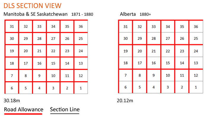
Many different surveys took place in the late 1800's, with two being prominently used today. Surveys that took place between 1871 to 1880 encompass most of southern Manitoba, parts of south eastern Saskatchewan and around the Prince Albert area. The important difference between the two survey methods are the width of the road allowances, and the frequency of road allowances in between each township.

Sections surveyed from 1871-1880 (Manitoba & SE Saskatchewan) contain road allowances that are 30.18m wide (1.5 chains), run north-south and east-west between all townships.

Sections surveyed from 1880 onward contain road allowances that are 20.12m wide (1 chain), but running east-west only fall on the north side of townships 7 to 12, 19 to 24, and 31 to 36. This results in a road allowance every mile progressing east-west and every two miles progressing north-south.


EDGE OF SECTION = EDGE OF ROAD ALLOWANCE


Hard Boundaries


Measured from the edge of the section in Alberta/Saskatchewan.

Measured from the middle of the road allowance in Manitoba.


*The above information should be used as guidelines only, and is based on past field experience. Clear Directional has made every effort to ensure the accuracy of the information contained within, and does not warrant nor guarantee the content.